Sıcaklık Artışı Nedeniyle Flaş Patlamasında Kısıtlanma
Kesintisiz flaşı, stroboskopik flaşı veya modelleme flaşının kısa aralıklarla tekrar tekrar kullanılması flaş kafasının, pilin ve pil kompartımanı yakınındaki alanların sıcaklığını artırabilir.
Üst üste flaş patlatma, flaş kafasının aşırı ısınma nedeniyle aşınmasını veya hasar görmesini önlemek için patlatma aralığını kademeli olarak yaklaşık 4 saniyeye kadar artırır. Bu durumda flaş patlatmaya devam ederseniz, flaş patlatması otomatik olarak kısıtlanır.
Flaş patlaması kısıtlandığında, yüksek sıcaklık uyarı simgesinin görüntülendiğini ve flaşlı çekim patlama aralığının otomatik olarak yaklaşık 8 veya 20 saniyeye ayarlandığını unutmayın (sırasıyla seviye 1 ve 2).
Sıcaklık Artışı Uyarısı
İki seviyenin her birinde, iç sıcaklık yükseldikçe farklı bir uyarı simgesi görüntülenir. Seviye 1'e ulaşıldıktan sonra flaş patlatmaya devam edersiniz durum seviye 2 olarak değiştirir.
| Ekran / Bip Sesi | Seviye 1 (Patlama Aralığı: Yakl. 8 sn.) |
Seviye 2 (Patlama Aralığı: Yakl. 20 sn.) |
|---|---|---|
| Simge | ||
| LCD panel aydınlatma | Yanar | Yanıp sönüyor |
| Bip Sesi | K.İş-06, [0] olarak ayarlandığında: Uyarı bip sesi duyulur | |
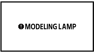
Modelleme lambası sıcaklığı artış uyarısı
Modelleme lambası ısındığında aşağıdaki uyarı görüntülenir.
Uyarıyı kaldırmak için doğrudan joystick tuşuna basın veya tuşuna basın.

Çevresindeki ortam sıcaklığı çok yükselirse modelleme lambası kararabilir veya kapanabilir.
| Ekran | Seviye 1 | Seviye 2 | ||
|---|---|---|---|---|
| Simge | ||||
| Açık olduğunda | Kapalı olduğunda | Açık olduğunda | Kapalı olduğunda | |
| Parlaklık | Maksimum parlaklığa ayarlandığında: karartılmış | Kapalı | ||
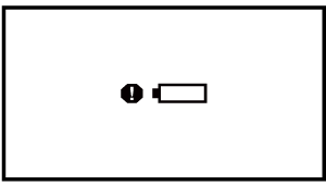
Pil sıcaklık artışı uyarısı
Pil ısındığında aşağıdaki simge görüntülenir. Ardından, ekran sıcaklık artışı uyarısı ile aynı duruma geri döner ().

Kesintisiz Flaş Sayımı ve Dinlenme Süresi
Aşağıdaki tabloda 1. seviye uyarı ekranına kadar tahmini sürekli flaş sayımı ve normal flaşlı çekime devam edilebilmesi için gereken tahmini dinlenme süresi gösterilmektedir.
Canon test standartlarına göre manuel flaş modunda ölçüldüğü gibi.
Önlem
-
Kesintisiz flaş patlattıktan sonra flaş kafasına, pile veya pil kompartımanının yakınına dokunmayın.
Kesintisiz flaşı veya modelleme flaşını kısa aralıklarla tekrar tekrar kullandıktan sonra flaş kafasına, pile veya pil kompartımanının yakınına dokunmayın. Flaş kafası, pil ve pil kompartımanının yakınındaki alan ısınabilir, bu da yanma riski oluşturur.
Önlem
- Flaş patlaması kısıtlanmışken pil kompartımanı kapağını açmayın veya kapatmayın. Bu, flaş patlaması kısıtlamasını iptal edecek ve bu da potansiyel olarak çok tehlikeli arz edecektir.
- Seviye 1 uyarısı görüntülenmese bile flaş kafası ısındıkça patlama aralığı uzar.
- 1. Seviye uyarı görüntülenirse, en az 50 dk. dinlenme süresi verin.
- Seviye 1 uyarısı göründükten sonra flaş patlatmayı bıraksanız bile, seviye 2 uyarısı görüntülenmeye devam edebilir.
flaş modunda veya yüksek sıcaklıklarda flaşlı fotoğrafçılık flaş sayımını tabloda belirtilenden daha erken kısıtlayabilir.
- Flaş sayımı önlemleri için Kesintisiz flaş patlatma önlemleri, Stroboskopik Flaş ve Modelleme Flaşı konularına bakın.
- Nadir de olsa yüksek sıcaklıklar gibi çevresel faktörler patlamayı engelleyebilir.
- Uyarı (Seviye 1) görüntülenene kadarki sürekli yanıp sönme sayısı, EL-1'in kendi başına kullanıldığı ve kompakt pil paketi CP-E4N (ayrı satılır) ile birlikte kullanıldığı zamandır. CP-E4N dışında bir harici güç kaynağı kullanıldığı zaman, uyarı görüntülenene (seviye 1) kadar patlatılan kesintisiz flaş sayısı daha az olur.
- Yansıma adaptörü kullanıldığında, renk filtresi kullanıldığında ve hem yansıma adaptörü hem de renk filtresi kullanıldığında uyarı görüntülenene patlatılan kadar kesintisiz flaş sayısı biraz daha az olur.
- K.İş-06, [1] () olarak ayarlandığında Speedlite’tan, patlama kısıtlandığında bile bir uyarı bip sesi duyulmaz.
- Ö.İş-22, [1] () olarak ayarlandığında, flaş kafası ısınsa bile LCD panel aydınlatması ile hiçbir uyarı verilmez.
- Kompakt Pil Paketi CP-E4N (ayrı satılır) kullanırken CP-E4N Kullanım Kılavuzuna da başvurun.