Camera Tracking Using Markers
You can print the markers provided for MREAL Platform and then use them for camera tracking.
Overview
Camera tracking can be performed by capturing placed markers with the MREAL Display. This is effective when there are few structures that can serve as feature points in the space. This facilitates an MREAL experience with higher accuracy than with spatial features ().

Points to Consider when Using Markers
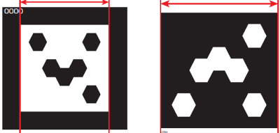
Marker size
-
The marker size (the length of one side inside the frame) is based on the usage range of the marker (the distance from the MREAL user to the marker).
- The usage range of a marker is 10 to 25 times the size of the marker (10 to 20 times with the A1 series). For example, when the marker size is 150 mm, the usage range will be approximately 1.5 to 3.75 m (approximately 1.5 to 3 m with the A1 series).
- If the MREAL experience area is large, determine the size of the main markers to be used based on the position where you want MREAL to be experienced with the most stable camera tracking.
- Determine the size of the other markers also according to the position of the MREAL experience.
Number of markers and placement
-
Place the markers so that there are at least three markers displayed in the images of the MREAL Display (A). When doing so, place the markers so that they appear at an angle (B).
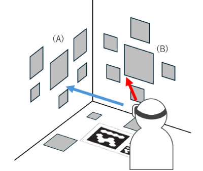
- Place the markers in locations close to where the 3D CG will be displayed.
- When an operation such as changing the position of a marker or deleting a marker has been performed, display the [Calibration Mode] tab in the Marker Tool window, and recapture the markers. For details, see “Registering Markers”.
Caution
- Affix cardboard or similar material to the back of the markers so that they do not bend, warp, or otherwise become deformed. If a bent or warped marker is used, the precision of camera tracking may deteriorate.
- Do not use multiple markers with the same ID.
- The images of markers may become small and camera tracking may become unstable depending on the position of the MREAL user. Placing markers of different sizes according to the area of the MREAL experience can help improve camera tracking stability.
Printing Markers
-
Launch Marker Print Tool.
Windows 11
- Click the [Start] button.
- Click [All apps], and select [Canon MREAL Platform 2025.x] > [Utility] > [MarkerPrintTool_x64].
- Select [MarkerPrintTool_x64] in Explorer.
Windows 10
- Click the [Start] button.
- Click [All apps], and select [Canon MREAL Platform 2025.x] > [Utility].
- Select [MarkerPrintTool_x64] in Explorer.
-
Set the marker specifications.
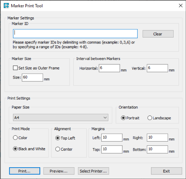
- Select the IDs of the required markers in [Marker ID]. 0 to 1023 are white, and 1024 to 2047 are black.
- Specify a marker size suitable for the purpose of use in [Marker Size]. The specified size is applied to all markers that were selected in [Marker ID].
- Specify the interval when multiple markers will be printed on one sheet of paper in [Interval between Markers]. Check the print layout in [Preview].
-
Set the print specifications and then print.
- Set the specifications in the items of [Print Settings].
- Click [Print] to print.
Registering Markers
Register the printed markers to the system.
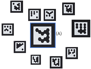
Preparation
Fix the markers to the floor in the MREAL space. When doing so, place markers of different sizes with marker (A) that will serve as the origin marker at the center.
Registration Procedure
-
Select [Basic Settings] in the MREAL Configuration Tool window.
-
Select [Use Marker Tool] in [Define World Coordinate System], and click [Start Tool].
-
Select [Capture by Camera Device] and click [OK] in the displayed window.
-
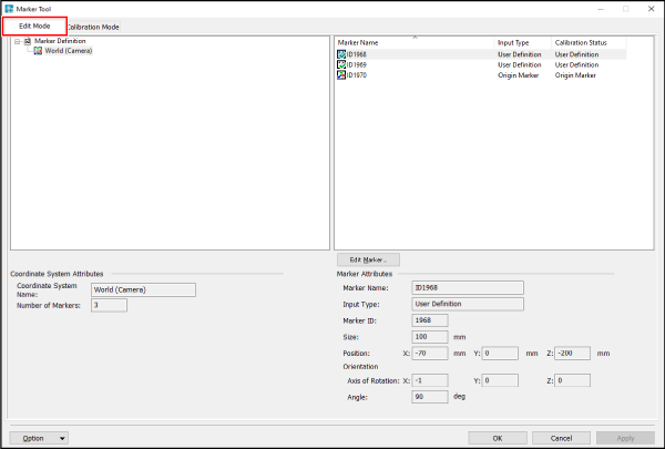
Select the [Edit Mode] tab in the Marker Tool window.
-
Delete the marker information.
-
Select all of the markers displayed in the list, then right-click and select [Delete from Marker Definition].
-
-
Register the origin marker.
- Right-click in the [Marker Name] list and select [Add MREAL Marker].
- Enter the ID and size of the marker you decided to use as the origin marker in the [Add MREAL Marker] window.
- Select [Origin Marker] from the [Input Type] list, and click [OK].
-
Register the other markers.
- Select the [Calibration Mode] tab in the Marker Tool window.
-
Click [Start] of [Auto-Capture] to capture the markers.
As shown below, capture all of the markers so that first the origin marker (A) is placed in the screen, and then a marker placed in the screen in the last capture is placed in the screen as with (B) and (C).
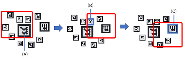
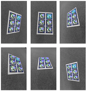
In addition, you can expect to improve the reading accuracy for camera tracking by repeatedly capturing while changing the direction as shown below.
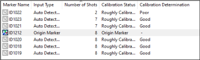
- When the markers are distinguished, the marker names and information are displayed in the list as shown below.
- When [Excellent] or [Good] is displayed for [Calibration Determination], click [Stop] of [Auto-Capture].
- Click [Calculate] in the displayed window.
- When [Calculation is finished.] appears, click [Close].
- Click [Apply] → [OK] on the [Calibration Mode] tab of the Marker Tool window.
Option Menu of Calibration Mode
The functions of the [Options] menu of the [Calibration Mode] tab in the Marker Tool window are as follows.
- [Image] allows you to load and save images captured in the calibration mode.
- Clearing the check mark from [Add Auto Detected Markers] allows you to set only the markers added in edit mode as the target for calibration.
-
[Detection Parameters...] displays the Adjust Detection Parameters window so that you can adjust the various thresholds.
[Adjust Performance] allows you to adjust the performance of marker recognition.
[Binarization Threshold] allows you to adjust the threshold for distinguishing black and white when recognizing markers.
[Minimum Marker Area] allows you to set the minimum area for recognizing markers.
If you place a check mark in [Automatic Detection Threshold], the above thresholds will be adjusted automatically.
If you place a check mark in [Render the processed image], image display is switched between binarization and multivalued.