Wireless Settings
- Setting as Sender
- Setting as Receiver
- Setting the Transmission Channel / Wireless Radio ID
 Lamp and Connection Indicator
- Sender Flash Firing On / Off
- Modeling Lamp Wireless On / Off
Set the sender and receiver for radio transmission wireless flash photography with E-TTL II / E-TTL autoflash as follows.
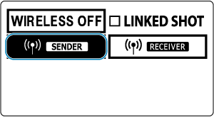
Setting as Sender
-
Select
 with the joystick.
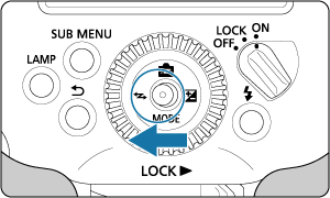
-
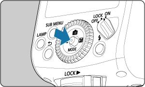
Set to

 .
.
- Press the joystick vertically or horizontally or turn
 to select , then push the joystick straight in.
- Press the joystick vertically or horizontally or turn
-
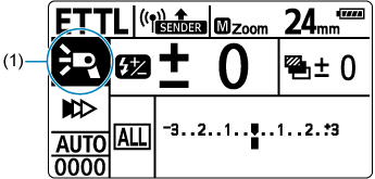
Select the firing method.
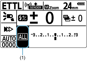
- Push the joystick straight in.
- Press the joystick vertically or horizontally or turn to select item (1), then push the joystick straight in.
- Press the joystick horizontally or turn to choose from
 ,
,  , or
, or  , then push the joystick straight in.
Setting as Receiver
-
Set to
 .
.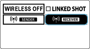
- Configure this setting on Speedlites to use as receivers.
- Select just as you set up the sender.
Caution
- Before normal flash photography, select
 to clear the wireless (sender/receiver) settings.
Setting the Transmission Channel / Wireless Radio ID
Set the sender's transmission channel and wireless radio ID as follows. Set the same channel and ID for both the sender and receivers. For receiver instructions, refer to the instruction manual of Speedlites equipped with radio transmission wireless receiver functionality.
Caution
- Set different wireless radio IDs for each channel, because interference between systems with Speedlites controlled by radio transmission may occur even if the units are set to different transmission channels.
-
Push the joystick straight in.
-
Select item (1).
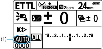
- Press the joystick vertically or horizontally or turn to select the channel item, then push the joystick straight in.
- Press the joystick vertically or horizontally or turn
-
Set a transmission channel.
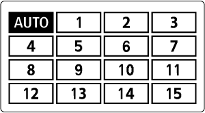
- Press the joystick vertically or horizontally or turn to choose from
 or channels 1–15, then push the joystick straight in.
- Press the joystick vertically or horizontally or turn
-
Select item (2).
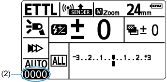
- Select the ID item just as you set the transmission channel, then push the joystick straight in.
-
Set the wireless radio ID.
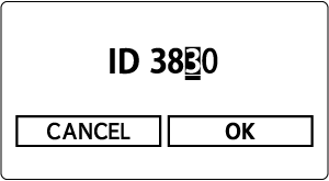
- Press the joystick horizontally or turn to select the position (digit) to set, then push the joystick straight in.
- Press the joystick vertically or turn to select a number in the range 0–9, then push the joystick straight in.
- Set a 4-digit number the same way, then select
 .
.
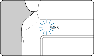
- The
 lamp is lit in green when communication is established between the sender and receiver.
- Press the joystick horizontally or turn
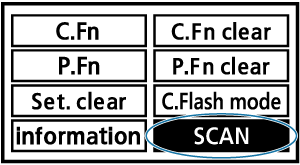
Scanning and setting sender transmission channels
You can scan radio signal conditions and then set the sender transmission channel automatically or manually. Setting the channel to [AUTO] will automatically reset the Speedlite to the channel with the strongest signal. When setting the channel manually, you can review scan results as you reset it.
-
Scanning when currently set to [AUTO]
-
Press the
 button.
-
Run the scan.
- Press the joystick vertically or horizontally or turn to select
 , then push the joystick straight in.
 - Select .
- The scan is performed, and the setting is reset to the channel with the strongest signal.
- Press the joystick vertically or horizontally or turn
-
-
Scanning when currently set to a channel (1–15)
-
Press the
button.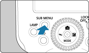
-
Run the scan.
- Press the joystick vertically or horizontally or turn to select , then push the joystick straight in.
- Select .
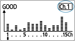
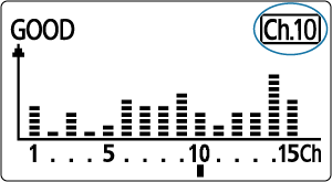
- The scan is performed, and a graph of signal conditions is displayed.
-
Higher peeks in the graph indicate stronger signals.
- Press the joystick vertically or horizontally or turn
-
Set the channel.
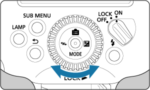
- Press the joystick horizontally or turn to choose a channel in the range of 1–15.
-
Push the joystick straight in to set the channel.
- Press the joystick horizontally or turn
-
Lamp and Connection Indicator
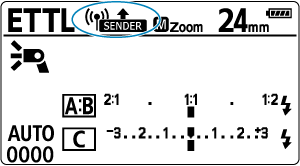
You can determine the connection status from the state of the ![]() lamp or the icon on the LCD panel.
lamp or the icon on the LCD panel.
| Status | Description | Action |
|---|---|---|
| Lit | Connected | – |
| Off | Not connected | Check the channel and ID |
| Off | Too many units | Do not exceed 16 senders and receivers, combined |
| Off | Error | Restart the senders and receivers |
| Lit | Connected*1 | – |
| Lit | Connected*2 | – |
1: When the sender side is connected to the sub-sender
2: When the sender side is connected for linked shooting
| Display | Description | Action |
|---|---|---|
| Connected | – | |
| Not connected | Check the channel and ID | |
| Too many units | Do not exceed 16 senders and receivers, combined | |
| Error | Restart the senders and receivers | |
| Connected*1 | – |
1: When the sender side is connected to the sub-sender
Caution
- Receivers do not fire unless the sender and receiver channels match. Set both to the same number, or set both to [AUTO].
- Receivers do not fire unless the sender and receiver wireless radio IDs match. Set to the same number.
Sender Flash Firing On / Off
You can set whether the sender fires along with the receivers it controls wirelessly. When sender flash firing is enabled, the sender fires as firing group A.
-
Push the joystick straight in.

-
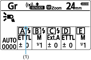
Select the item shown in (1).
- Press the joystick vertically or horizontally or turn to select the item, then push the joystick straight in.
- Press the joystick vertically or horizontally or turn
-
Set sender flash firing.
- Press the joystick horizontally or turn to enable or disable sender flash firing, then push the joystick straight in.
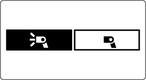
 : Sender flash firing ON
 : Sender flash firing OFF
- Press the joystick horizontally or turn
Note
- Disabling sender flash firing expands the available flash output range from 1/1024 to 1/8192.
Modeling Lamp Wireless On / Off
The modeling lamp of connected sender/receiver units turns on and off in response to pressing the sender ![]() button when the EL-5 is a sender or receiver. This way, you can check subject shadows created by multiple Speedlites simply by operating the sender. Pressing the sender camera shutter button completely also turns off the modeling lamp of receivers.
button when the EL-5 is a sender or receiver. This way, you can check subject shadows created by multiple Speedlites simply by operating the sender. Pressing the sender camera shutter button completely also turns off the modeling lamp of receivers.
Caution
- When sender flash firing is disabled, the
 button does not activate the sender modeling lamp.
 - Modeling lamps of firing groups set to
 flash mode and other non-firing groups are not activated.
 - Any changes to flash modes or firing groups while a modeling lamp is on do not alter the current illumination status of the lamp. Before changing these settings, turn off the sender modeling lamp as needed.
Note
- Receiver modeling lamps can be turned on or off even by a sub-sender.
- Brightness and duration of modeling lamp illumination depends on the settings of each receiver.
- As an indicator of modeling lamp illumination commands,
 (1) on firing group control information does not necessarily correspond to the current status of receiver modeling lamps.