Part Names
- LCD Panel
- Battery Charger LC-E6 (Sold Separately)
- Battery Charger LC-E6E (Sold Separately)
- Included Accessories

- (1)Catchlight panel (shown stowed)
- (2)Wide panel (shown stowed)
- (3)Flash head (light-emitting unit)
- (4)Modeling lamp / AF-assist beam emitter
- (5)Mounting foot
- (6)Mounting foot locking pin
- (7)Battery compartment cover
- (8)Contacts
- (9)Mounting foot cover
Note
- Not equipped with remote release terminal (release cable SR-N3 cannot be used).

- (1)
 Radio transmission confirmation lamp
 - (2)LCD panel
- (3)
 Sub menu button
 -
(4)
 LAMP button
 - (5)
 Undo button
 - (6)Mounting foot lock lever
- (7)Lock-release button
- (8)Bounce angle index
- (9)Joystick
 Menu direct
 Flash mode
 Wireless / linked shooting setting
 Flash exposure compensation / flash output setting
 - (10)Power switch
 Power ON
 Button / dial lock (Power ON)
 Power OFF
 - (11)
 Flash-ready lamp / test flash button
 - (12)
 Select dial
 - (13)Dust-proof and drip-proof adapter
LCD Panel
E-TTL II / E-TTL autoflash ()

- (1)
 Flash exposure compensation
 -
(2)
 E-TTL II / E-TTL autoflash
 /
/  /
/  Custom flash mode*1
 -
(3)
 Standard
 Guide number priority
 Even coverage
 Bounce upward
 Bounce downward
 Temperature increase (flash firing restriction)
 Modeling lamp lit
 -
(4)
 First-curtain sync (normal shooting)
 Second-curtain sync
 High-speed sync
 - (5)Flash exposure compensation amount
- (6)Effective flash range / shooting distance
 Value in meters
 Value in feet
-
(7)
 Charge indicator
 Auto
Auto Manual
 -
(8)
 Zoom indicator
 Wide panel + bounce warning
 Out of flash coverage range warning
 - (9)Flash coverage (focal length)
- (10)Battery level indicator
- (11)
 Flash exposure bracketing
 - (12)FEB sequence
- (13)Flash exposure level
- (14)
 Aperture value
1: The flash mode is identified after the indicator for the current Custom flash mode.
Manual flash ()

-
(1)
 Manual flash
/ / Custom flash mode*1
Manual flash
/ / Custom flash mode*1 - (2)Manual flash output
- (3)Manual flash level
1: The flash mode is identified after the indicator for the current Custom flash mode.
Stroboscopic flash ()

-
(1)
 Stroboscopic flash
/ / Custom flash mode*1
Stroboscopic flash
/ / Custom flash mode*1 - (2)Flash frequency
- (3)Flash count
1: The flash mode is identified after the indicator for the current Custom flash mode.
Radio transmission wireless flash photography ()
-
Sender unit

-
(1)
 Configured as a sender
 Configured as a sub-sender
 -
(2)
 Radio transmission wireless
-
(3)Flash mode
E-TTL II / E-TTL autoflash Manual flash Stroboscopic flash
 Group firing / / Custom flash mode*1
 -
(4)
 Sender flash firing ON
 Sender flash firing OFF
- (5)Firing group control
-
(6)
 Transmission channel
 Transmission channel set automatically
 - (7)Wireless radio ID
- (8) Sender / receiver charge indicator
- (9)
 Modeling lamp indicator
 - (10) Receiver fully charged
- (11)Flash ratio
1: The flash mode is identified after the indicator for the current Custom flash mode.

- (1) Receiver fully charged
- (2)Firing group control
- (3)Sender / receiver charge indicator
- (4) Modeling lamp indicator
- (5)Group firing mode*1
1:
Group firing onlyNote
- is no longer displayed after senders and receivers in radio transmission wireless flash photography are fully charged.
 ,
,  ,
,  , and
, and  are available as flash modes for group firing.
- As an indicator of modeling lamp illumination commands, on firing group control information does not necessarily correspond to the current status of receiver modeling lamps.
-
(1)
-
Receiver unit

- (1)
 Receiver
 - (2) Transmission channel
- (3)Wireless radio ID
-
(4)
 Test flash
 Remote release
 Modeling flash
 - (5)
 Configured as a receiver
- (1)
Radio transmission: linked shooting ()

-
(1)
 Linked shooting
/ / Custom flash mode*1
Linked shooting
/ / Custom flash mode*1 -
(2) Configured as a sender
Configured as a receiver
- (3)
 Release*2
1: The flash mode is identified after the indicator for the current Custom flash mode.
2: ![]() Only when configured as a sender.
Only when configured as a sender.
Battery Charger LC-E6 (Sold Separately)
Charger for Battery Pack LP-EL.

- (1)Battery slot
- (2)Charge lamp
- (3)Power plug
Battery Charger LC-E6E (Sold Separately)
Charger for the Battery Pack LP-EL.

- (1) Charge lamp
- (2) Battery pack slot
- (3) Power cord
- (4) Power cord socket
Included Accessories
-
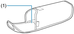
Speedlite case
(1) Mini stand storage pocket
-
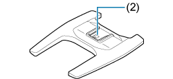
Mini stand
(2) Mounting part
-
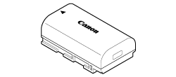
Battery Pack LP-EL