Nomenclature

- (1)Catch light panel (stowed state)
- (2)Wide panel (stowed state)
- (3)Flash head (Light-emitting unit)
- (4)Color filter detector
- (5)External flash metering receiver
- (6)Optical transmission wireless receiver
- (7)AF-assist beam emitter
- (8)Mounting foot
- (9)Locking pin
- (10)Contacts
- (11)External power source socket
- (12)Bounce adapter detector
- (13)Terminal cover
- (14)Battery compartment lid
- (15)Battery compartment cover lock
- (16)Sync terminal
Note
- Not equipped with remote release terminal (release cable SR-N3 cannot be used).

- (1)Bounce adapter / color filter attachment part
- (2)
 Radio transmission confirmation lamp
 - (3)LCD panel
- (4)
 Sub menu button
 - (5)
 LAMP button
 - (6)
 Undo button
 - (7)Mounting foot lock lever
- (8)Lock-release button
- (9)Bounce angle index
- (10)Bounce lock-release button
- (11)Joystick
 Zoom
Zoom Flash mode
 Wireless / linked shooting setting
 Flash exposure compensation / flash output setting
 - (12)Power switch
 Power ON
 Button / Dial Lock (Power On)
 Power OFF
 - (13)
 Flash-ready lamp / test flash button
 - (14)
 Select dial
 - (15)Dust-proof and drip-proof adapter
LCD Panel
E-TTL II / E-TTL Autoflash (), Continuous Shooting Priority Mode ()

- (1)
 Flash exposure compensation
 - (2)
 E-TTL II / E-TTL autoflash
 Continuous shooting priority mode
 - (3)
 Standard
 Guide number priority
 Light distribution priority
 Top bounce
 Bottom bounce
 Bounce adapter attached
 Color filter attached
 Temperature increase (flash firing restriction)
 Modeling lamp lit
 - (4)
 First-curtain sync (normal shooting)
 2nd-curtain sync
 High-speed sync
 - (5)Flash exposure compensation amount
- (6)Effective flash range / shooting distance
 Meter display
 Feet display
- (7)
 Charge indicator
 Automatic setting
 Manual setting
 - (8)
 Zoom display
 Wide panel + bounce warning
 Out of flash coverage range warning
 - (9)Flash coverage (focal length)
- (10)Battery level display
- (11)
 FEB
FEB - (12)FEB sequence
- (13)Flash exposure level
- (14)
 Aperture value
Manual Flash ()

- (1)
 Manual flash
 - (2)Manual flash output
- (3)Manual flash level
Stroboscopic Flash ()

- (1)
 Stroboscopic flash
 - (2)Flash frequency
- (3)Number of flashes
Auto / Manual External Flash Metering ()

- (1)
 Auto external flash metering
 Manual external flash metering
 - (2)
 ISO display
- (3)ISO speed
Radio Transmission Wireless Shooting / Optical Transmission Wireless Shooting ( / )
-
Sender unit(s)

- (1)
 Sender setting
 Sub sender setting*1
 - (2)
 Radio transmission wireless
 Optical transmission wireless
 - (3)Flash mode E-TTL II / E-TTL autoflash Manual flash Stroboscopic flash
 Group firing*1
 - (4)
 Sender flash firing ON
 Sender flash firing OFF
- (5)Firing group control
- (6)
 Transmission channel
 Transmission channel automatic setting*1
 - (7)Wireless radio ID*1
- (8) Sender / receiver charge indicator
- (9)
 Synchronization speed warning*1
 - (10) Receiver charging completed*1
- (11)Flash ratio
1:
Radio transmission wireless only
- (1) Receiver charging completed*1
- (2)Firing group control
- (3)Sender / receiver charge indicator
- (4)Group firing mode*2
1:
Radio transmission wireless only2:
Group firing onlyNote
- During radio transmission wireless shooting, when the sender and receiver are fully charged, disappears.
- For group firing, you can select the and the flash mode from


 .
.
- (1)
-
Receiver unit

- (1)
 Receiver
 - (2) Transmission channel
- (3)
 Test flash*1
 Remote release*1
 Modeling flash*1
- (4)
 Receiver setting
 - (5)
 Individual receiver*2
1:
Radio transmission wireless only2:
Optical transmission wireless only - (1)
Radio Transmission: Linked Shooting ()

- (1)
 Linked shooting
 - (2) Sender setting Receiver setting
- (3)
 Release*1
1: ![]() Sender setting only
Sender setting only
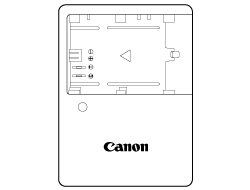
Battery Charger LC-E6
Charger for the Battery Pack LP-EL.

- (1)Battery mounting part
- (2)Charge lamp
- (3)Power plug
Battery Charger LC-E6E
Charger for the Battery Pack LP-EL.

- (1) Charge lamp
- (2) Battery pack slot
- (3) Power cord
- (4) Power cord socket
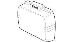
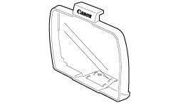
Accessories Provided
-
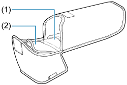
Speedlite case
(1) Mini stand storage section
(2) Bounce adapter / color filter housing unit
-
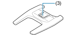
Mini stand
(3) Mounting part
-
Bounce adapter SBA-EL
-
Color filter SCF-ELOR1
-

Color filter SCF-ELOR2
-
Battery Charger LC-E6/LC-E6E*
-

Battery Pack LP-EL
Battery Charger LC-E6 or LC-E6E is provided (The LC-E6E comes with a power cord).