Part Names

- (1)
 Mode button
 - (2) Movie shooting button
- (3) Strap mount
- (4)
 Main dial
 - (5) Shutter button
- (6)
 /
/ Multi-function/FTP server image transfer button
 - (7) Self-timer lamp/AF-assist beam
- (8) Grip (battery compartment)
- (9) DC coupler cord hole
- (10) Depth-of-field preview button
- (11) Contacts
- (12) Lens mount
- (13) Shoe cover
- (14) Flash sync contacts
- (15) Multi-function shoe
- (16) RF lens mount index
- (17)
 Focal plane mark
 - (18) Strap mount
- (19) Tally lamp
- (20) Shutter curtain/Image sensor
- (21) Lens release button
- (22) Lens lock pin
- (23) Remote control terminal
- (24) Body cap

- (1) LCD panel
- (2) Eyecup
- (3) Speaker
- (4) Microphone
- (5)
 /
/ Still photo shooting/movie recording switch
 - (6) Terminal cover
- (7)
 External microphone IN terminal
 - (8)
 Digital terminal
 - (9) Exhaust vent
- (10)
 Headphone terminal
 - (11)
 HDMI OUT terminal
 - (12)
 Sync terminal
 - (13)
 /
/ LCD panel info switching/illumination/cropping button
- (14) Power/multi-function lock switch
- (15)
 Quick control dial 2
 - (16)
 AE lock button
 - (17)
 AF point selection button
 - (18)
 AF start button
 - (19)
 Multi-controller (can also be pressed straight in)
 - (20)
 Quick control dial 1
 - (21)
 Set button
 - (22)
 Erase button
 - (23)
 Playback button
 - (24)
 Menu button
 - (25)
 /
/ Rating/voice memo button

- (1) Viewfinder eyepiece
- (2) Screen
- (3) Accessory positioning hole
- (4) Intake vent
- (5) Tripod socket
- (6) Serial number (body number)
- (7) Accessory positioning hole
- (8) Access lamp
- (9) Dioptric adjustment knob
- (10)
 Magnify/reduce button
 - (11)
 Info button
 - (12)
 Quick Control button
 - (13) Card slot cover
- (14) Battery compartment cover lock
- (15) Battery compartment cover
- (16) Card slot 1
- (17) Card slot 2
- (18) Card eject button
LCD panel information display
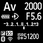
Information displayed varies depending on camera status. For icon details, see Information Display.
Viewfinder information display
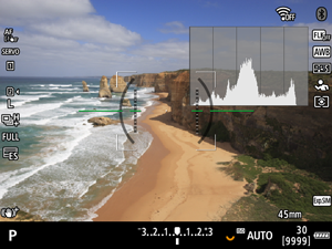
Information displayed varies depending on camera status.
Battery Charger LC-E6
Charger for Battery Pack LP-E6P/LP-E6NH/LP-E6N/LP-E6 ().

- (1) Battery slots
- (2) Charge lamp
- (3) Power plug
Battery Charger LC-E6E
Charger for Battery Pack LP-E6P/LP-E6NH/LP-E6N/LP-E6 ().
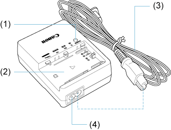
- (1) Charge lamp
- (2) Battery pack slot
- (3) Power cord
- (4) Power cord socket
Attaching the Strap
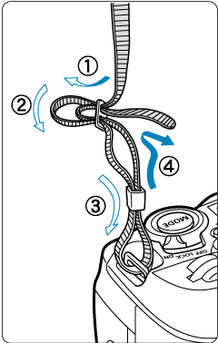
Pass the end of the strap through the strap mount from the bottom, then pass it through the strap buckle as shown. Pull the strap to take up any slack and make sure the strap will not loosen from the buckle.
Using the Cable Protector
When connecting cables (an interface cable or HDMI cable), use the included cable protector. Using the cable protector helps prevent accidental disconnection and terminal damage.
- When connecting the camera to a computer, use a Canon cable (included or sold separately).
- When connecting the camera to a television or other display device, use a commercially available HDMI cable.
Preparation
-
Prepare the cable protector.
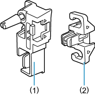
- The cable protector consists of the protector (1) and a clamp (2).
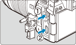
-
Attach the protector to the camera.
Cable insertion/connection
Insert the cables in the clamp, attach the clamp to the protector, then connect the cables to the camera.
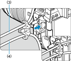
With both a Canon interface cable and an HDMI cable
-
Pass each cable through the clamp.
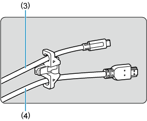
- (3) Canon interface cable
- (4) HDMI cable
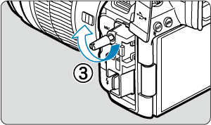
-
Attach the clamp to the protector.
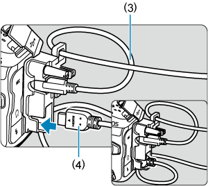
-
Connect each cable to the camera.
With only a Canon interface cable or HDMI cable
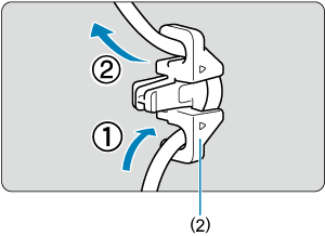
Pass the cable through the clamp (2) as shown, then attach the clamp to the protector.
Caution
- Using the camera when an interface cable or HDMI cable is connected without the cable protector may damage the camera terminal. Make sure each cable is securely connected to the camera terminal.